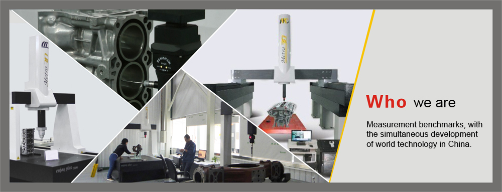


Precision assessment criteria for CMM
The precision assessment criteria for the CMM: ISO 10360
In 1994, ISO10360 International standard “Acceptance, Test and Re-Test of CMM” became effective. This standard indicates the basic steps for the test of CMM. The national measuring machine standard GB/T16857.2-1997 “Coordinate Metrology - Section 2: Performance Test of CMM ” being implemented in China is equivalent to the ISO standard.
There are six sections under the headings – ISO 10360 “Product Geometrics Technical Specifications – CMM Acceptance, Test and Retest”:
— Section 1: Terminology;
— Section 2: CMM measuring the linear dimensions;
— Section 3: CMM with the rotary table axis as the fourth axis;
— Section 4: Scanning type CMM;
— Section 5: CMM with multi-styli probing system;
— Section 6: Error assessment for calculation of Gaussian associated features.
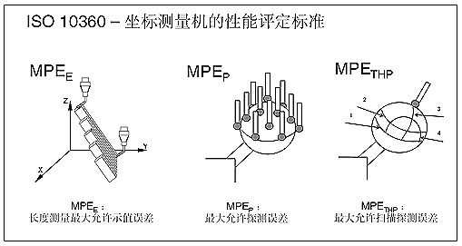
ISO standard comprises three main parameters: maximum permissible indication error of length measuring (MPEE), maximum permissible probing error (MPEP); maximum permissible scanning probing error for scanning measuring (MPETHP)
Prior to the purchase of the measuring machine, the users should be familiar with the acceptance standard of CMM. The following is the brief introduction to the ISO 10360:
ISO 10360-1 (2000) “Terminology”;
Section 1 of the standard defines the terminology related to CMM such as “probing system” or “standard ball”. Thus, we don’t restate it here.
ISO 10360-2 (2001) “CMM measuring linear dimensions”;
(MPEE) and Max. permissible probing error (MPEP).
Max. permissible indication error of length measuring (MPEE):
Measure five dimensions of measuring blocks in 7 positions of the measuring volume and each block length will be measured three times and all results must be within the range indicated by MPEE.
Max. permissible probing error (MPEP):
Use 25 points to measure the precision standard ball with the probing points distributed evenly. The max. permissible probing error MPEP is the maximum value of all the measured radius.
ISO 10360-3 (2000) “CMM with the rotary table axis as the fourth axis”;
As for the measuring machine with rotary table, the measuring error is defined in the section, which mainly contains three indices: radial four axis error (FR), tangential four axis error (FT) and axial four axis error (FA).
ISO 10360-4 (2003) “Scanning type CMM”;
This section is applicable to the CMM with continuous scanning functions. It indicates measuring error under the scanning mode.
Most CMM manufacturers defined “space scanning probing error under THP”. Besides this, the standard also defines scanning probing error under THN, TLP and TLN.
Max. permissible scanning probing error (MPETHP):
Scan along the four routes given in standard ball; max. permissible scanning probing error MPETHP is the max. difference value of all the scanning radius. Note: The THP instructions must contain the total measuring time, for example, THP= 1.5um (scanning time is 72 seconds). The THP describes the scanning characteristics on the point with most density that is scanned along the known routes. ISO 10360-4 further indicates that TLP: scan with low density points along the known routes. THN: scan with high density points along the unknown routes and TLN: scan with low density points along the unknown routes.
- PREV:How to select proper styli
- NEXT:nobody


Address:U Valley, Liandong, 328 Chengkang Road, Chengyang District, Qingdao, China. Postcode:266100
Telephone:+86-0532-87602111 E-mail: info@metro-3d.com 鲁ICP备14028182号-2
